Assembly Editor
Open a CAT Assembly Asset to arrange Part Models and other Assemblies into an authored, reusable structure.
Editor layout
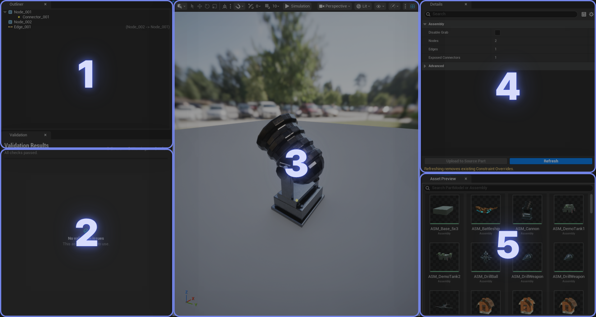
- Outliner: Review the root Part, child Parts, Connectors, and the relations between them.
- Validation: Check structural errors and warnings before saving the Assembly.
- Viewport: Preview the Assembly, select Parts or Connectors, and run the editor simulation.
- Details: Edit the selected Assembly, Part, Connector, or relation. Refresh and Upload to Source Part are also available here.
- Asset Preview: Select the Part Model or Assembly to add next.
Assembly workflow
- Create or open a CAT Assembly asset.
- Select the Part Model or Assembly to add from Asset Preview.
- Click a compatible Connector in the viewport to place it.
- Repeat as needed, then save the Assembly.
Selecting an asset and clicking a compatible Connector creates the connection and updates the Outliner.
Assembly overrides
Overrides let an Assembly customize a specific Part or connection while keeping its source Part Model unchanged. Any property without an override continues to use the source definition.
Body Override
A Body Override replaces the source Body definition for one selected Part instance inside the current Assembly. Select the Part, then enable Override Source Body under Body Override in Details.
Use it to customize Body properties such as the Mesh and Materials, local Transform, Physics Mode, Physical Material, Mass, or Collision Profile for this Assembly only. It does not modify the source Part Model or other Assemblies that use it.
When to use it
Use a Body Override when a reused Part needs different mass, Materials, or physics settings in one Assembly. If several Assemblies need the same change, edit the Part Model or promote the change with Upload to Source Part instead.
Edge Override
An Edge Override is a placement adjustment owned by the edge that connects two Parts. Select the connection relation in the Outliner or viewport, enable Edge Override in Details, then edit its Location and Rotation.
The override replaces the body-local frame of the existing parent Part's Endpoint B Connector for this Assembly only. This lets you fine-tune where and how the Parts meet without changing the Connector in the source Part Model.
An Edge Override changes only the Connector position and rotation. It does not store scale or change the constraint's allowed degrees of freedom. Rotation axes and movement limits still come from the original Connector Profile.
Override scope
A Body Override belongs to one Part node, while an Edge Override belongs to one Part connection. Both are local changes stored in the current Assembly.
Damage and durability
Damage and durability belong to the relation between two Parts, not to either Part itself. Select the connection relation in the Outliner or viewport, then configure it under Constraint Rule in Details.
- Enable Damage: Allows this connection to receive durability damage and break.
- Durability: The connection's maximum durability, or starting HP. Higher values withstand more damage.
At runtime, applied damage is subtracted from the relation's current durability. When it reaches zero, CAT breaks that relation. If the relation was the only path joining sections of the Assembly graph, the structure can split into separate Assemblies.
Damage requires gameplay logic
Enabling damage does not make collisions or projectiles deal damage automatically. On authority, find the target CAT Relation and call Apply Durability Damage. Pass damage calculated by a projectile hit, explosion, or Gameplay Behavior Feature to this function.
Grabbed Assemblies
Durability damage is rejected while an Assembly is actively grabbed because it is being handled as a placement ghost. Apply the damage again after the grab ends.
Synchronize Assembly and source Parts

These commands move changes in opposite directions. Choose the command based on where the latest edit was made.
Refresh
Direction: Source Part Models → current Assembly
Use Refresh after editing a source Part Model. CAT reloads every referenced Part Model, rebuilds the Assembly snapshot, and updates node transforms from the source Connectors.
Edge Overrides
Refresh removes all Edge Overrides in the current Assembly. If any exist, the editor asks for confirmation. You can undo the operation with Ctrl+Z.
Upload to Source Part
Direction: Selected Assembly Part → source Part Model → selected referencing Assemblies
Use Upload to Source Part when an adjustment made in the Assembly should become the reusable Part Model definition. Select a Part or one of its Connectors, then click the button. After saving the source Part Model, choose any other referencing Assemblies that should also be refreshed.
What is uploaded
CAT writes the selected Part's local Body, Actuator, and Connector transform overrides to the source Part Model. The Connector Profile continues to define the allowed degrees of freedom. Assemblies refreshed afterward receive the new source data and discard the corresponding local overrides.